
The inline appliance can be deployed using one of three topologies, depending on the routing and switching infrastructure already in place at the deployment site.
Placement Considerations
Before selecting one of the three inline deployment models below, two physical and network constraints determine where the appliance can actually go regardless of which topology is used.
- Traffic Intersection: the inline appliance acts as a transparent Layer-2 bridge and can intersect any arbitrary link in the network. The physical medium of that link (RJ-45, SFP, or SFP+) determines which NICs and transceivers the appliance needs (see Section 2, Hardware, for compatibility).
- Subscriber Traffic Visibility: Preseem associates traffic to subscribers by IP address, so the appliance must intersect the network on the private (pre-NAT) side. If Preseem sits downstream of NAT, subscriber IP addresses are no longer visible and per-subscriber attribution won't work. This constrains where in the topology any of the three models below can be placed
1. Inline with OSPF Bypass
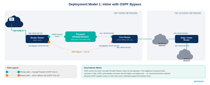
A Border Router (handling BGP/NAT to the internet) and a Core Router (handling VPLS, PPPoE, or similar toward the backhaul/access network) are connected to each other two ways: a primary path that runs through the inline appliance, and a direct point-to-point bypass link between the two routers that does not pass through Preseem. OSPF is configured so the path through Preseem carries a lower cost (e.g., cost 1) than the direct bypass link (e.g., cost 10), making the Preseem path preferred under normal operation. If the appliance is powered down, removed, or fails, OSPF automatically fails over to the higher-cost bypass link, so subscriber traffic keeps flowing without it.
- Requires OSPF-capable routers on both sides of the appliance.
- Requires an additional physical link between the Border Router and Core Router dedicated to the bypass path.
- Provides automatic, protocol-level failover with no manual intervention if the appliance goes down.
2. Layer-2 Hairpin (Switch-Centric)
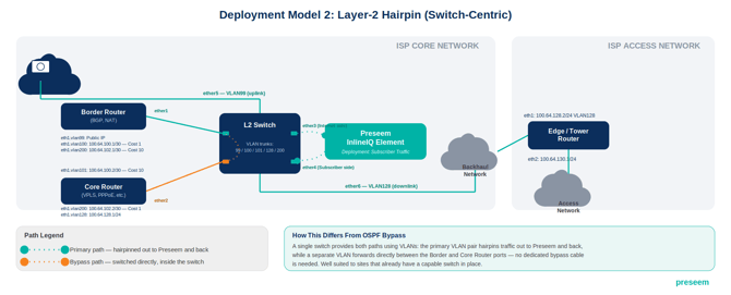
A switch sits between the Border Router, the Core Router, and the inline appliance, and VLAN trunking is used to “hairpin” traffic out to the appliance and back rather than cabling the appliance directly between two routers. The Border Router and Core Router each connect to the switch over their own VLAN-tagged sub-interfaces (for example, a dedicated VLAN carrying the public-IP/internet-facing path and separate VLANs for the OSPF-costed primary and bypass paths), and the switch directs the appropriate VLAN traffic through the appliance's bridge ports.
- Suited to sites that already have a capable switch in place and would rather avoid running an additional direct bypass cable between routers.
- Relies on the switch's VLAN trunking and tagging being configured correctly; misconfigured VLANs are a common source of connectivity issues in this model.
- Can still combine with OSPF cost differentials carried over the VLAN trunks for failover, similar in effect to the direct bypass model above.
3. Simple Inline Deployment (Single Router, No Bypass)
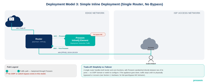
A single router performs both border and core functions (e.g., BGP/NAT and PPPoE) rather than splitting them across two devices, and the inline appliance sits directly between that router and the access network with no OSPF bypass link and no switch hairpin.
- The simplest of the three models to cable and configure — well suited to smaller sites with a single router and no OSPF domain to extend.
- Has no automatic failover path: if the appliance goes down, subscriber traffic stops until it is physically bypassed or the appliance recovers. Bypass-NIC/fail-open hardware behavior is covered in Section 2, Hardware (currently flagged there as a documentation gap).
Understanding Dataplane Transparency: DPv1 vs. DPv2
Both Dataplane 1 (DPv1) and Dataplane 2 (DPv2) function as Layer 2 “bump-in-the-wire” devices: neither acts as a routed Layer 3 hop, neither decrements the IP packet's TTL, and neither alters MAC or IP headers. In that strict protocol sense, both versions are transparent to the network around them. DPv2 was in fact architected for even greater Layer 2 transparency than DPv1, passing frames like 802.1ad (QinQ) through without any further configuration. See Section 4 Configuration - VLANS for details
The distinction this manual draws between the two is operational, not a difference in OSI-layer behavior. It's about what happens to subscriber traffic if the Preseem service itself stops, fails, or is restarted:
- DPv1 uses a native Linux kernel bridge (br0) between two NIC interfaces. That bridge is a kernel-level construct: it keeps forwarding traffic between the two interfaces regardless of whether Preseem's services are running.
- DPv2 does not use a kernel bridge at all. Paired interfaces instead form a link group, and the preseem-netdev-manager service, running in userspace, handles every packet's forwarding and enforcement directly. If that service stops, fails, or is restarted, there is no kernel-level fallback: packets stop passing between the interfaces entirely.
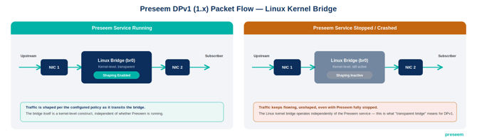 DPv1 packet flow: the kernel bridge keeps forwarding traffic (unshaped) even with the Preseem service fully stopped.
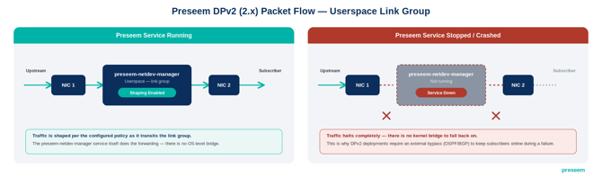
DPv2 packet flow: with no kernel bridge to fall back on, traffic halts completely when the service is down.
This is why a DPv2 deployment must include an external bypass, OSPF or BGP, per the deployment models in this section to keep subscriber traffic flowing through a failure scenario. DPv1's kernel bridge made that unnecessary; DPv2's userspace design does not offer the same fail-open behavior.
Verifying the Deployment
Regardless of which model is used, verify the deployment before declaring it complete:
- Confirm both bridge interfaces show link up
- Confirm traffic is actually passing through the appliance (not just linked)
- Check for common miswiring symptoms such as one side up and the other down, which usually indicates a swapped port or a mismatched transceiver (see Section 2, Hardware, for NIC and transceiver compatibility).